INSTRUCTIONS
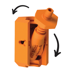
Step 1
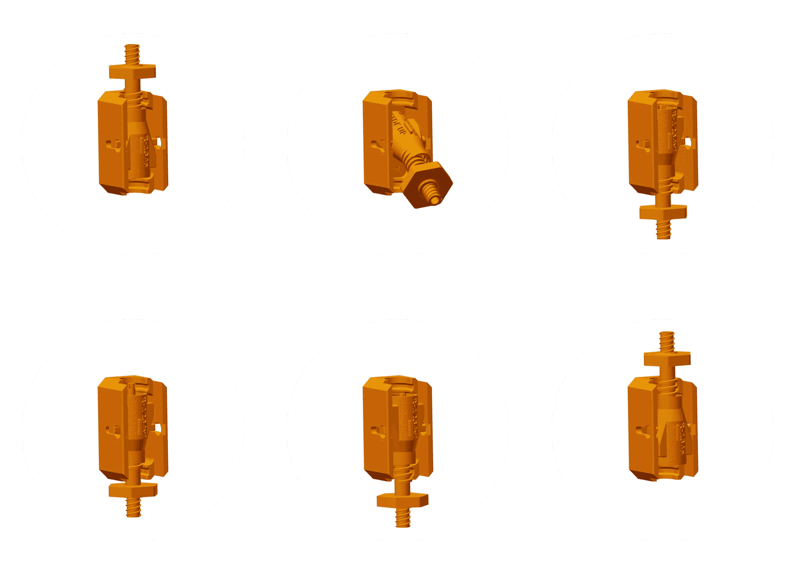
Identify refrigerant system type (see owner’s manual) and prepare adapter. Holding the dual-adapter in hand, pivot the inner body to either R-134a or R-1234yf SIDE UP, respective to your system type.
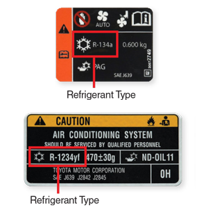
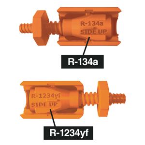
Step 2
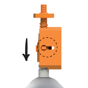
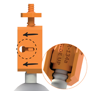
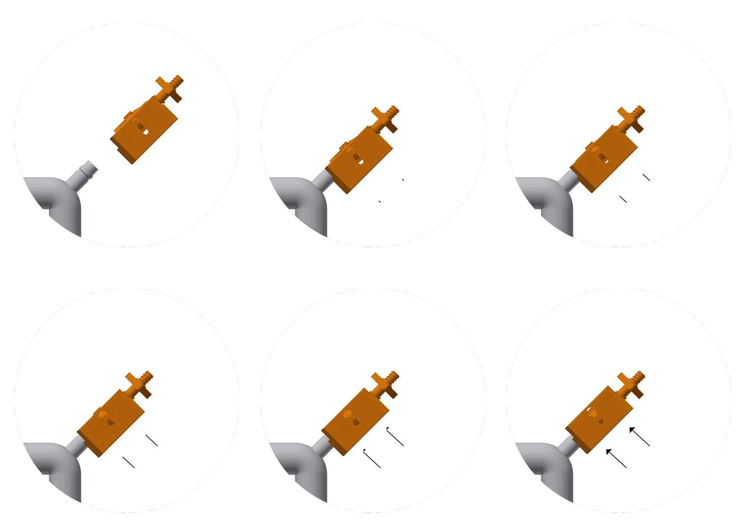
Locate the low-side A/C service port. Push the adapter onto low-side service port.
NOTE: Make sure outer slide is pushed backward away from inner body (see dotted line).
Step 3
Push outer slide forward to lock adapter into place.
NOTE: Connection should feel tight, not loose. If a loose connection is made, adapter will not work properly. Repeat Step 2 until tight connection is made.

Step 3
Push outer slide forward to lock adapter into place.
NOTE: Connection should feel tight, not loose. If a loose connection is made, adapter will not work properly. Repeat step 2 until tight connection is made.
Step 4
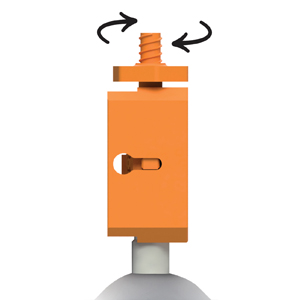
Turn knob clockwise to engage service valve and secure a connection.
NOTE: Make sure to turn the knob all the way down – resistance is normal.
Step 5
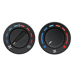
Before injecting dye, start the engine and adjust the A/C to the maximum cooling level.
Caution: Beware of moving engine parts.

Step 5
Before injecting dye, start the engine and adjust the A/C to the maximum cooling level.
Caution: Beware of moving engine parts.
Step 6
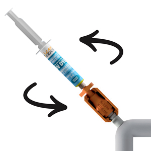
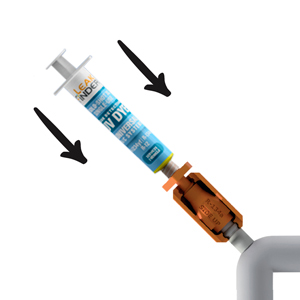
Remove syringe cap and screw tip into adapter’s receiving port.
Step 7
Push firmly down on syringe plunger and inject dye into your system. Once plunger is empty, disconnect and dispose. Allow 5-10 minutes for dye to circulate while vehicle is running.

Step 7
Push firmly down on syringe plunger and inject dye into your system. Once plunger is empty, disconnect and dispose. Allow 5-10 minutes for dye to circulate while vehicle is running.
Step 8
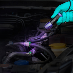
Turn off the engine. Inspect possible leak areas with LeakFinder® leak detection flashlight. Leaks will glow bright green.
Step 9
After the leaks are repaired, clean the remaining dye from the leak sites with dye cleaner or shop cleaner.
Step 10
Run the A/C system for another 5-10 minutes and reinspect with flashlight. No glows means that all leaks have been repaired.
Step 9
After the leaks are repaired, clean the remaining dye from the leak sites with dye cleaner or shop cleaner.
Step 10
Run the A/C system for another 5-10 minutes and reinspect with flashlight. No glows means that all leaks have been repaired.
NOTE: The LF100CS comes with an optional flexible extension hose.
Before connecting the syringe to the dual adapter (as depicted in Step 6), first attach the extension hose to the syringe. Next, press down on the syringe plunger to advance a small amount of dye through the empty hose (a small amount of dye should appear at the end of the extension hose). This step will purge the hose of air and is necessary for injection. Lastly, connect the syringe with its purged extension hose to the dual adapter and inject dye into the system (Step 7).
DUAL ADAPTER
ADAPT
Identify refrigerant system type (R-1234yf or R-134a) and prepare adapter.
CONNECT
Connect the adapter to the low-side service port.
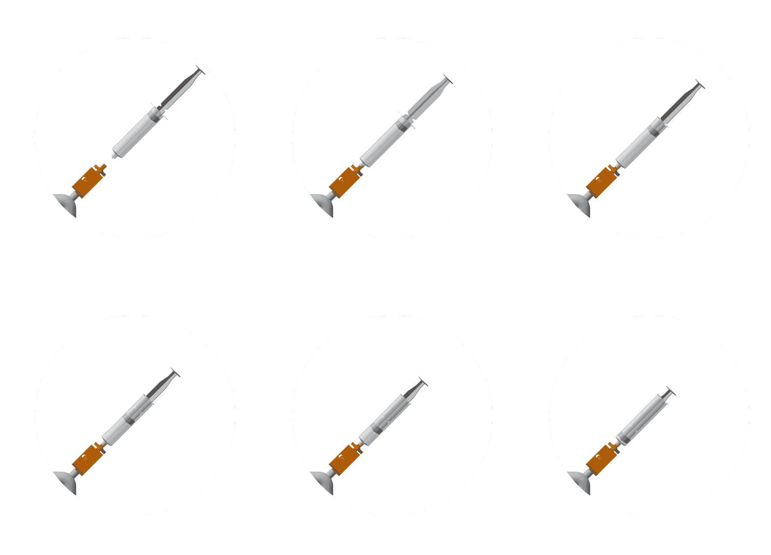
INJECT
Install the syringe and inject dye.
DETAILS
• LeakFinder® Universal UV Dyes provide the most precise leak detection for all automotive A/C systems containing R-134a, R-1234yf, or other widely used refrigerants.
• Can be safely added to the system. The dye will not affect the system lubricant properties or change how the equipment works.
• LeakFinder® dyes find the smallest and most problematic leaks that would otherwise be impossible to detect.
• Compatible with EV/Hybrid. Safe to use in electrically driven A/C compressors.
IMPORTANT
• Wear protective glasses or goggles while working on any A/C systems.
• For vehicle A/C systems, use the entire LeakFinder® universal A/C dye prefilled syringe to service single vehicle.
• Adapter is intended for single-use.
• Prior to injecting LeakFinder universal A/C dye prefilled syringe into an A/C system, inspect the service port (s) and valve cores for damage.
Product Troubleshooting
If the LF100CS Adapter is accidentally disassembled, please reference the diagram below and follow the instructions. A product animation is also available and provides a visual reference for reassembly.
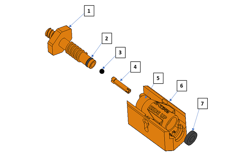
LF100CS ADAPTER | ||
ITEM | QTY | DESCRIPTION |
1 | 1 | KNOB |
2 | 1 | O-RING |
3 | 1 | BALL |
4 | 1 | PIN |
5 | 1 | INNER BODY |
6 | 1 | OUTER SLIDE |
7 | 1 | GASKET |
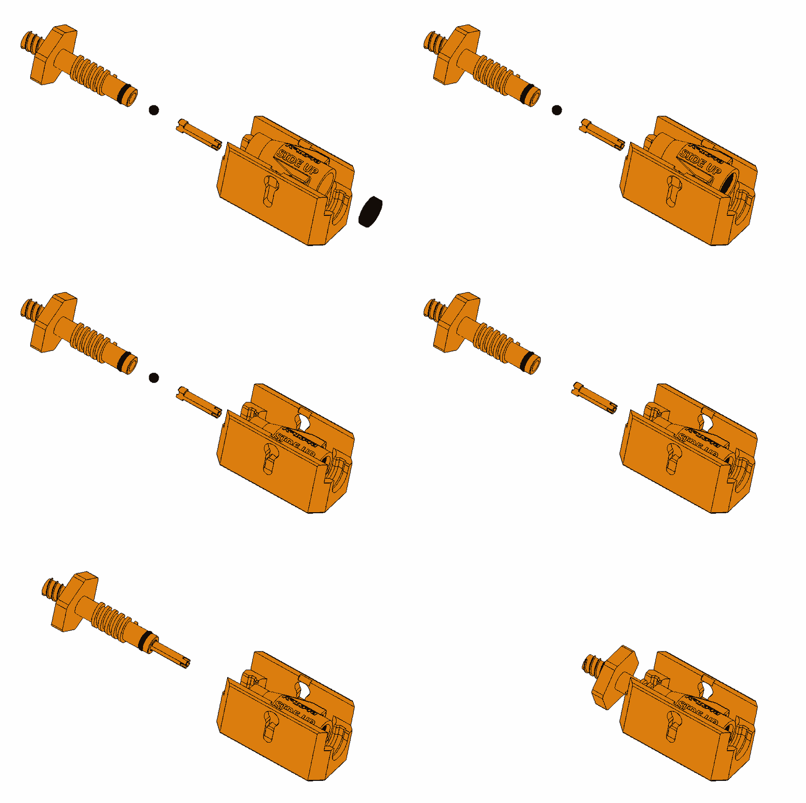
If the gasket (Item 7) is disconnected, firmly reseat the gasket in the outer slide (6). If the knob (1) is disconnected from the adapter, first ensure the ball (3) is inserted in the knob’s lower opening and then continue to place the pin (4) in the knob’s opening as well. Next, turn the knob clockwise into the top of the outer slide (6). The knob and the outer slide are now secured, and the LF100CS adapter is ready for use.
WARNING: Keep out of reach of children. Wash thoroughly after handling. Wipe all spills to avoid stains. Store in a cool place away from sunlight. Store in climate controlled, dry area. Store 40-100˚F (4.4-37.7˚C). Dispose of in accordance with all local, state and federal regulations.